Powerful ventilation forms a key part of the safety systems in the Channel Tunnel Rail Link tunnels

Phil Doyle General Manager, Contracts, Senior Hargreaves

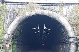
UNLIKE their counterparts beneath the English Channel, the twin-bore running tunnels on Section 2 of the Channel Tunnel Rail Link are not provided with a parallel service tunnel. If a serious incident occurs, passengers will be evacuated though cross-passages protected by fire doors into the adjacent bore, which will function as both refuge and emergency exit.

The ventilation systems will be regulated to pressurise the safe tunnel, admitting fresh air and keeping smoke and fumes away from the escaping passengers. The same controls will be used to manage airflow in the incident tunnel, maximising visibility for the emergency services.

Ventilation system design for CTRL Section 2 was undertaken by consultants Parsons Brinckerhoff, who had to model both the everyday needs of regular operations and the behaviour of the system in an emergency. Powerful fans will ensure the reliable control and delivery of fresh air in a non-emergency, if a train has to be held in a tunnel or during maintenance work.

London tunnels

The two twin-bore tunnels run up to 40m beneath the London suburbs, with service shafts to provide ventilation, power and staff access. Because of the ability to control the airflow through the subterranean network, only three service shafts were required on the 10·5 km Ripple Lane to Stratford tunnels, and two on the 7·5 km Stratford - Gifford Street tunnels.

Each shaft houses twin ducts with reversible fans to inject or extract air from the tunnel. Because an incident could arise anywhere, all fans and ductwork are fire rated to withstand extended exposure to high temperatures.

Inside the tunnels are high-level reversible jet fans which can induce airflow in either direction to support the flow from the shaft fans. A monitoring and control system from Johnson Controls directs the airflow, to deal with daily or emergency needs.

Because the London tunnels pass beneath built-up areas, attenuators have been fitted above and below the fans to prevent noise break-out. The fans are also sprung, and have flexible plastic connecting skirts to avoid vibrations setting up resonance in the ductwork.

Under the Thames

Ventilation in the 3 km bores beneath the River Thames has to differ from the two land tunnels, as it would have been difficult and expensive to sink suitable shafts close to the banks of the river.

Instead of shafts, plant rooms have been built at both ends of each bore, incorporating a bank of four powerful 1·6m diameter 155 kW fans specially built by Fläkt Woods. Only three fans are required to deliver the required air volume of 175m3/sec, with the fourth providing continuity during maintenance.

These fans drive air through a Saccardo nozzle, a tapered chamber which discharges air through a narrow slot high in the tunnel at an exit velocity of 34m/sec. Fans at both ends of a tunnel being used for evacuation will give sufficient pressure to prevent ingress of smoke from the adjacent tunnel, while use of a Saccardo nozzle at one end of the incident tunnel will reduce the risk to the emergency services.

Careful planning

Contractors on the CTRL project are required to guarantee their fixed equipment for 25 years, and so all the ductwork, working platforms and support steelwork supplied by Senior Hargreaves is galvanised or hot metal sprayed.

A further consideration is the need to withstand the rapid swing between extremes of large positive and negative air pressures as trains pass at up to 230 km/h. To withstand these forces, Senior Hargreaves fabricated the ductwork in heavy gauge metal with added reinforcement.

Each shaft on the London tunnels contains around 100 tonnes of ventilation equipment, with the structural steelwork and platforms alone amounting to 30 tonnes. Attenuators add a further 30 tonnes, and pressure relief dampers almost 20 tonnes. Assembly was a major challenge, and the very limited on-site storage space available meant that hundreds of individual elements needed to be built and moved on-site in a precise sequence. In addition, bulk loads had to be kept off the local roads at peak times.

Installation of the sophisticated safety systems on the final link between the Channel Tunnel and London has been a massive effort of civil and mechanical engineering, but it is one which we hope passengers will remain unaware of as they speed below.

  • CAPTION: Banks of powerful fans force air into the Thames tunnel bores, delivering fresh air during regular operation and creating a pressurised refuge in an emergency

Topics