


BYLINE: Harry Hondius MSc
NEXT SPRING, the Lirex experimental diesel railcar developed for German Railway is to be converted into a hybrid electro-diesel trainset, with the replacement of one diesel generator set by a 15 kV 162/3Hz transformer.
The new medium-frequency ’e-transformer’ is being developed jointly on an exclusive basis by Alstom LHB GmbH and SMA Regelsysteme GmbH, of Niestetal near Kassel. SMA supplied the first auxiliary inverters for Lirex. A 120 kW DC/DC converter stabilises the variable 700V to 1·8 kV supplied by the generator/rectifier to 650 V. This feeds two 35 kVA inverters for the air-conditioning units, another 35 kVA inverter supplying three-phase 440V 50 Hz, and two 220A, 24V DC battery chargers.
Alstom ordered similar SMA inverters for the 18 dual-system and 10 diesel-electric hybrid RegioCitadis trams for RBK in Kassel. These inverters will all be fed with 400 to 950V DC, either by a four-quadrant rectifier from the 15 kV 162/3 Hz overhead, from the 600V DC tramway catenary or the variable voltage from the diesel generator. Two 13 kW inverters serve the 400V three-phase AC supply and 465A 28V for the battery charger. One 18 kVA/15 kW inverter serves the three air-conditioning packs at 80 to 440V DC, 10 to 50 Hz.
The 1500 kW ’e-transformer’ consists of three main elements. The input inverter is a frequency modifier and voltage splitter. This takes 15 kV 162/3Hz from the catenary via a self-induction coil, flattening the sinusoid wave, and feeds a 110A supply to four double-cascade modules arranged in series. Equipped with 6·5 kV IGBTs, these computer-controlled modules take a variable input voltage of between 1·4 and 2·5 kV 162/3Hz, and the output is 1·8 kV 5kHz. Communications are handled by a CAN bus and high speed optic fibre links. Seven modules are necessary to handle the power requirements, and the eighth provides a degree of redundancy. In the event of any defect in a module, a computer controlled mechanical switch cuts it out.
The 2·3MW medium-frequency transformer takes the 8 x 1·8 kV 5kHz supply from the input unit via eight primary windings around a common ferrite core. One secondary winding provides an output of 1650V 5kHz. The two sets of windings are cooled by separate circuits, using a synthetic ester coolant known as Midel.
The final element is a four-quadrant controller which rectifies the 1650V AC output to DC. This is the intermediate link voltage for existing Onix inverters, that each feed three AC traction motors rated at 190 kW using Alstom’s Agate control system. The four-quadrant controller also permits regenerative braking energy to be fed back into the 15 kV supply.
The whole assembly, without the cooling equipment, is installed in a GRP container with a laminated carbon membrane to provide protection against electro-magnetic interference. Overall dimensions of the container are 2100 x 2735 x 580mm, and the total weight is around 3 tonnes - half that of conventional transformer.
Continuous rating for the e-transformer is 1500 kW, but the power draw can be increased to 2250 kW for a 30sec burst every 15min. Overall efficiency is greater than 93%, with a very flat curve across the power range.
Work has now started on the development of a two-system version able to accept 25 kV 50Hz. If this is successful, Alstom plans to use the e-transformer on a wide range of EMUs, even in the high speed range.
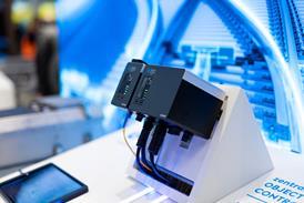
CAPTION: The Alstom e-transformer. To the left are the eight cascade modules, in the centre the medium frequency transformer, and on the right the four-quadrant controller feeding the Onix inverters