


INTRO: The 18·4 km priority section of experimental Superconducting Maglev guideway was formally opened on April 3, and the first levitation trials are due to take place next month. Murray Hughes reports from the Yamanashi test centre
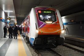
JAPANESE Minister of Transport Makoto Koga and Yoshiyuki Kasai, President of JR Central, took part in ceremonies on April 3 (inset right) marking the official opening of the 18·4 km priority section of the 42·8 km maglev test line near Otsuki in Yamanashi prefecture.
The first levitation tests are due to get under way next month - levitation has not been possible until now because the lift forces using superconducting maglev technology are not strong enough to raise the train off the guideway until it is moving at around 200 km/h, and the train has not yet been authorised to reach this speed.
When I visited the site on March 11 the three-car train was undergoing low-speed running trials using linear motor power - the three-phase coils forming the stator of the linear motor are installed in the sidewalls of the guideway, and speed is controlled by varying the frequency of the power passing through the coils.
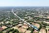
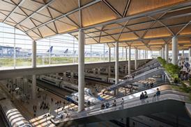
The test centre is located near Otsuki, where the maglev test guideway is carved through the hills and mountains not far from the Mt Fuji range. A viewing platform on the roof of the five-storey control centre overlooks the double track guideway opposite a substation, offering a panorama over the Ogatayama bridge where the guideway crosses the Chuo Expressway. A public viewing area is being completed in an adjacent building.
General Manager of the Yamanashi maglev test centre Akio Seki said the principal objective of the project was to develop a form of transport capable of carrying large numbers of people between Tokyo and Osaka in 1h. To this end the Yamanashi test site has been built so that it can eventually form part of the proposed Chuo Shinkansen.
Seki set out the detailed programme of trials to date. Although the train arrived in the depot located at the Tokyo end of the priority section in July 1995 (RG 10.95 p631), it was not until December 1996 that all the equipment had been assembled and checked ready for running tests to begin.
Seki says that about 10 days were spent testing the vehicles in the depot, moving them short distances, and this was followed by ’adjustment tests’ on the guideway. For about two weeks the train was hauled on its retractable rubber-tyred wheels in unpowered mode on the guideway by a special maintenance tractor without the linear motor equipment being activated; this was then switched live and a similar period was spent testing in this mode.
During this period the checks included correct detection of the train’s position by inductive loop and its speed. The cumulative running distance on March 10 was 979·8 km, and Seki said that the 1000 km mark would be passed on the day of my visit. The maximum speed achieved by that date was 104·4 km/h.
Seki says three years of tests are planned. The first year will be devoted to ’basic running’. The initial test period will see the train run on rubber tyres at speeds that will increase to 150 to 200 km/h to achieve levitation. Once levitated, the gap between guideway and vehicle will be around 100mm, and the landing wheels and horizontal guide wheels will be retracted.
The second year is designated for ’general function tests’. With a second train due to arrive in October, trials will include passing at high speed. The double track section near the Otsuki control centre has one track laid out for 550 km/h, and one where speed will not exceed 440 km/h. Asked why the speed was not identical, Seki informed me that it was to save costs.
’Continuity tests’ with the trains running between adjacent guideway sections controlled by different substations will also be undertaken during this phase of the tests, and a series of safety trials will also be carried out.
In the third year efforts will be concentrated on endurance running, and Seki says that many visitors will be invited to sample high-speed levitated travel.
Assessment by committee
At the end of the three-year period, an evaluation committee will assess the project and deliver a verdict by the end of JR Central’s 1999 financial year. Established by the Ministry of Transport in January this year, the committee is made up of MoT staff, academic experts in the fields of electrical, mechanical and civil engineering, specialists in bio-electromagnetics, railway experts, and the project team leaders.
Seki said that it was important to test the key technologies: safety, braking, train protection and the train’s articulation. He mentioned that a major concern was to prevent the occurrence of ’quench’, or sudden loss of the magnetic field. He said that this had happened on the Miyazaki test track in 1987 with the MLU002 vehicle, and considerable efforts were being devoted to ensure that it could not happen on the Yamanashi track. ’We have moved from a test project to one that is designed for commercial service, so safety and reliability are more important.’
Seki said that another target was to keep magnetic fields below 20 gauss, and for this reason a magnetic shield is provided between the interior panelling of the train and the main insulation material in the bodyshell. Fully enclosed gangways also incorporating magnetic shields will take passengers from the terminal to the vertically opening vehicle doors which will align with the gangways; there will be no open platforms at maglev stations.
According to Seki, only if the 20 gauss minimum is achieved will the train be permitted to carry the public. When I boarded the train on March 11, I was advised to hand my credit cards to staff outside the guideway.
Airline interior
The air-conditioned interior is strongly reminiscent of an airliner, reflecting the use of aircraft technology to reduce weight. Window size (400mm deep by 300mm wide), folding over-seat luggage lockers and the 2+2 seating layout are comparable too; the seat pitch has been set at 880mm.
Seat belts offered further evidence of aircraft practice. Seki said that the belts were fitted while confirmation of the train’s safe operation is being sought. Once established, the belts would be removed. On commercial maglev trains seat belts would not be required.
There is no cab at the front of the train as the train control function is carried out from the ground. A small crew compartment is fitted behind the leading levitation bogie, and here it is possible to view the guideway ahead of the train on a monitor linked to a camera in the nose. There are communications links to the ground control centre, while various displays show the status of on-board equipment.
Should the train encounter an obstruction on the guideway, special guards fitted in the nose will thrust aside small objects such as birds. Larger objects will cause crumpling of a buffer zone, so absorbing the shock of a collision.
Further development
Over the next few months Seki’s test engineers will be seeking methods of cutting the amount of heat generated in the cryostats, and making the refrigeration plant more reliable.
The vehicles will be tested to check how successful the semi-monocoque design of aluminium alloys is in achieving low aerodynamic resistance and weight. Weight of an intermediate car body is just 2·6 tonnes compared with 6 tonnes for a Series 300 car. Fatigue testing of a full-size model of a bodyshell has already been carried out, and the test engineers will now seek to verify the results by checking the vehicles’ ability to withstand repeated variations in pressure as they run in and out of tunnels. Most of the priority test section, 16 km, is in tunnel, and 11·4 km is double track. When the rest of the trial section is built, there will be 24 km of double track, and 34·6 km in tunnel. An early decision is needed to build the remaining 25 km, but this will depend on the early results of trials on the priority section.
Braking methods
The on-board power supply, provided by a gas turbine on the first train, will be checked for reliability, and the different types of brake will be trialled to ensure that they can stop the train reliably from 500 km/h. Initial braking trials were under way on March 11 using the aerodynamic brakes that fold up from the roof above each bogie; there are three single panels and one twin panel forming a pair of ’ears’ at the Tokyo end of the train.
Other forms of brake include a regenerative brake that reverses the current in the guideway coils and returns power to the supply company. A rheostatic guideway brake is provided by making the linear motor act as a generator, with kinetic energy being consumed in resistances. Finally, disc brakes of carbon resin and carbon fibre composites are fitted to the undercarriage wheels to bring the train to a standstill. Use of multiple layers of rubber to achieve high levels of heat resistance in the tyres is intended to ensure that the train can ’land’ safely at 550 km/h in an emergency. One bogie has been fitted with drive equipment that starts the wheels rotating before landing.
When the second experimental train arrives on site in October, it will comprise four cars, one of which is a stretched design (Fig 1). It is designed to be reformed as a five-car set by taking the intermediate car from MLX-01. The ’aero-wedge’ and ’double-cusp’ noses are retained, but the ends are reversed so that aerodynamic trials of both shapes can be compared.
Among equipment to be tested is a resiliently-mounted levitation bogie (Fig 2) that is intended to improve ride comfort. In addition to the air spring between body and bogie on MLX-01, it will incorporate another air spring between the bogie and the superconducting magnet. Also intended to raise the ride quality is an active suspension system.
The principal innovation will be an inductive on-board power supply (Fig 3) to replace the gas turbine on MLX-01.
Infrastructure
Three types of guideway have been installed on the priority section: panel, beam and direct attachment. In the panel configuration the coils are attached at an on-site factory to concrete panels which are then installed in the guideway. The beam configuration has the coils attached in the factory to concrete beams that take the place of the sidewalls. With the direct-attachment method the coils are fixed to the sidewalls on site. The guideway coils are made of aluminium conductors insulated with plastic.
There are also three types of pointwork. Developed from earlier installations on the Miyazaki test track, the hydraulic traverser turnout has a moving section 88·2m long. The diverging route can be taken at up to 70 km/h. The electric version has a 73m moving section, and maximum speed on the diverging route is 45 km/h.
For depots and terminals a moving-sidewall turnout has been developed. Vehicles will be able to take the diverging route at 45 km/h on their landing wheels.
None of the three types of turn-out should take longer than 20s to operate.
Trains entering the Kuki tunnel on the priority section at over 500 km/h could generate a compression wave travelling at the speed of sound that may create a sonic boom at the other end of the bore. To decrease the pressure gradient of the compression wave and avoid a boom, a 100m long hood has been constructed at one end of the tunnel.
Asked about costs, Seki said that the budget available for construction of the 42·8 km test track was ´300bn, but he was unable to say how much of this had been spent on building the priority test section.
JR Central has paid for 94% of the cost of the infrastructure, with local government funding the other 6%. The cost of the vehicles, electrical converters, and control systems which need technical development, is shared by national government (25%), JR Central (35%), the Railway Technical Research Institute (30%) and local government (10%). Seki said that some costs have also been borne by industry. o
CAPTION: MLX-01 crosses the Ogatayama bridge over the Chuo Expressway near Otsuki
CAPTION: Top: ’Aero-wedge’ nose at the Tokyo end of MLX-01; General Manager of the Yamanashi maglev test site Akio Seki looks on from the viewing platform on the roof of the control centre
Inset: Murray Hughes and Akio Seki try out the seats in the Kofu end leading car of the MLX-01 train
CAPTION: Fig 1. Layout of JR Central’s second experimental maglev trainset includes a stretched intermediate car offering 70 seats; the standard length intermediate car would have 62 seats. Overall length will be 101·9m
CAPTION: Above: Moving sidewall turnout developed for low-speed applications in depots and terminals with the vehicles running on their landing wheels
Upper and lower left: Electrically powered traverser switch permits trains to take the diverging route at 45 km/h
CAPTION: Aerodynamic brakes being trialled outside the Otsuki test centre
CAPTION: ’Double-cusp’ end of MLX-01; a camera is mounted in the small window
CAPTION: Two designs of boarding gangway are on test: ’extension type’ (left) and ’swinging-door type’ (right)
CAPTION: Fig 2 (below). The second test train will have resiliently mounted bogies (right); the rigidly mounted bogie (left) is fitted on the first train
Fig 3 (bottom). Inductive power collection on the second train. Current is induced in the upper part of the levitation guidance coil (1), and then passes to the lower portion (2). This produces a magnetic field in the on-board power collection coil (3)
CAPTION: Section of guideway in tunnel; there would be numerous long tunnels on the Chuo Shinkansen where it passes through Japan’s Central mountain range
Depot keeps the magnets cool
The depot at the Tokyo end of the priority section has two tracks, one able to accommodate five trains and the other four. Equipment is provided to support the trains so that the levitation bogies or tyres can be exchanged. Daily inspections will be carried out here.
The depot houses the equipment to cool the helium needed for the trains’ superconducting magnets to a temperature of -269°C. When a train returns to the depot, evaporated helium gas is recovered, purified and reliquefied for storage or re-use. Facilities are also provided for storing liquid nitrogen, used as a supplementary coolant.
Before a train leaves the depot, its superconducting magnets are precooled and filled with liquid helium. On-board refrigeration is also needed as the liquefied helium evaporates as heat is generated while the vehicle is running. The refrigeration capacity of the MLX-01 is 60% higher than that used on the MLU002N test vehicle on the Miyazaki test track. Liquid helium and liquid nitrogen tanks are fitted on top of the superconducting magnets.
To maintain superconductivity as long as possible, the superconducting coils comprise ultra-fine multi-filament wires made of a niobium-titanium alloy embedded in a copper matrix; the wires are cooled in the liquid helium to -269°C
Technical data
Main technical data of JR Central’s MLX-01 Superconducting Maglev train
Train
Number of cars 3
Overall length mm 77600
Number of levitation bogies 4
Length of leading car mm 28000
Length of intermediate car mm 21600
Cross-sectional area m2 8·9
Height, levitated mm 3280
Height, on landing wheels mm 3320
Levitation height mm 100
Seats, Kofu end car 46
Seats, Tokyo end car 30
Twin seat width mm 1060
Gangway width between seats mm 470
Width mm 2900
Weight, fully loaded tonnes
Leading car 32
Intermediate car 20
Bodyshell, intermediate car 2·6
Guideway
Length of priority section km 18·4
Maximum grade % 4
Minimum horizontal curve radius m 8000
Minimum vertical curve radius m 37000
Distance between guideway centres m 5·8
Maximum cant 10°
Internal tunnel height (double track) m 7·7
Internal tunnel width (double track) m 12·6
L’ouverture de la voie de guidage à sustentation magnétique présage deux ans d’essais
Le tronçon prioritaire de 18·4 km de la voie expérimentale à sustentation magnétique supraconductrice a été officiellement ouvert le 3 avril. Les premiers essais de sustentation commencent le mois prochain lorsque le train d’essai aura atteint la vitesse de 200 km/h nécessaire pour réaliser une sustentation suffisante. Avec un deuxième train qui doit arriver au centre d’essais dans la préfecture de Yamanashi, un programme d’essais intensif aura lieu pour démontrer que la construction d’une ligne à sustentation magnétique entre Tokyo et Osaka offrant un trajet d’une heure, est une proposition techniquement réalisableEr