


This article has been prepared by the Railway Technical Research Institute, with assistance from the Japan Railway Construction, Transport & Technology Agency and the Technology Research Association for Gauge-Changing Trains
ANOTHER phase of development work is underway with Japan's variable-gauge EMU. Built in the late 1990s, the train has already undergone a programme of research and testing that included a spell at the Transportation Technology Center in the USA.
Further technical development is needed because of the complexity of the project. The design and construction of wheelsets and bogies is more intricate than in the case of a train built to change gauge between 1435mm and a typical broad gauge such as the 1520mm in Russia or 1668mm in Spain - apart from anything else, there is less space available to accommodate the equipment.
All bogies have to be powered, partly because of the need to operate at high speed, but also to ensure that traction is available from some bogies when the train is passing through a gauge-changing installation; this makes the bogie design very complicated. Not only that, but the Japanese train must be able to demonstrate excellent running stability on the Shinkansen network and when operating at high speed through curves on conventional 1067mm gauge track.
When the prototype gauge-changing train was first built, it was fitted with two types of bogie. The Type A bogie uses a direct drive with the motor mounted directly on the side of the wheel, which rotates independently rather than being affixed to an axle; a wheelset steering mechanism is also fitted. The Type B bogie has a conventional motor and a cardan shaft drive to a gearbox on the axle. Both types allow the train to change gauge without stopping, passing through the gauge-changing installation at up to 10 km/h (above).
Two variants of the Type A bogie were developed, the RT-X9 and the RT-X10. Both have the same type of wheel, but the RT-X9 is bolsterless and has a steering mechanism with direct mechanical connections to the car body. In contrast, the RT-X10 has a steering system with a steering beam that is independent of the car body. The Type B bogie, which was fitted to the middle car, is known as the RT-X11.
Type A bogie
The wheelset of the Type A bogie is shown in Fig 1. The axle does not rotate and has guide beams on both sides. The guide beam has two pins on each side which can slide vertically within the bogie, allowing the guide beams and axle to move vertically with the pins; however, the axlebox and axle remain fixed in the longitudinal direction by the guide beam. An outer sleeve is fitted on the axle, along which it can slide. Fixed on the outer sleeve are a sliding bearing and the inner stator of the traction motor; the rotor is mounted directly on the wheel, as are the brake discs.
A locking block is inserted into the outer sleeve with a spline so that it cannot rotate but is fixed to the sleeve; the locking block can move vertically in the axlebox. Two dowels are located on the top of the block, one for the narrow gauge position and the other for standard gauge operation; the dowel fixes the wheel gauge when it is inserted into the locating space in the axlebox.
Type B bogie
Fig 2 shows the Type B bogie and wheelset. The axle is driven by the gearbox and supported by thrust bearings in guide beams on each side. The guide beam and axlebox beam are connected by spherical bearings so that the axle and axlebox beam are fixed in the longitudinal direction. The axle has an outer sleeve, with a spline inside. The inner race of the spline is fixed on both sides of the axle, so the axle and outer race are connected by the roller spline and can rotate together. The wheel is pressed on to the outer sleeve, on which taper roller bearings are mounted.
The axlebox has a locking block on each side. Between the locking block and the axlebox beam is a 'stopper' that fixes the wheel gauge by insertion into the hole of the axlebox beam and locking block. During the gauge-changing process the outer sleeve assembly with wheel, taper roller bearing and axlebox slides along the axle.
The stopper in the locking mechanism (Fig 3) moves vertically in the axlebox beam; it is forced downward by a spring and has a working arm at the bottom. The working arm is connected to a locking arm and releasing arm by a small axle, which rotate together.
The gauge-changing process was fully described in RG 3.99 p156. Briefly, when the train enters the gauge changing installation, the axleboxes ride up onto special support rails, releasing the weight of the carbody from the wheels. A locking arm unlocks the wheels so that they are free to slide on the axles as they follow the tapered guide rails. Once the wheels are in their new position, they are locked into place. The axleboxes are then released from the support rails and the train is able to continue on the new gauge.
Test programme
Running trials began in January 1999 on JR West's San-in line. The train was then sent to the Transportation Technology Center in Pueblo, Colorado, where it ran on standard gauge track from April 1999 until the end of January 2001. Returning to Japan, it underwent speed trials and tests in sharp curves on JR Kyushu's Nippo line in November 2001 and February 2002. From April to June 2003 it was tested on JR Shikoku's Yosan line, returning to the Nippo line in June 2004.
From August to October 2004 trials were carried out on the Sanyo Shinkansen, reaching a maximum speed of 210 km/h.
After this phase of testing was completed, the train was taken out of service in preparation for another phase of trials that centre on an improved bogie design.
The second generation bogies have been developed from the Type B bogie with some important technical changes and improvements which will take the project a stage further towards commercial operation.
The main features of the second generation bogie are:
- better high speed running stability, requiring the rotational direction gap between the wheels and the axle to be small;
- improved high speed curving performance with the axlebox suspension stiffness optimised;
- high reliability of the gauge-changing system, with an improved locking mechanism;
- higher braking capacity;
Fig 4 shows the second-generation bogie, which has been built in two versions. In one variant the gearbox is located in the centre of the axle with the brake units mounted on the bogie frame. The second version has an offset gearbox and wheel-mounted disc brakes.
Bench testing of the second-generation bogies has already started, and this work is due to be finished by the end of the year. Next year they will be fitted to the test train for dynamic trials.
Further developments will depend on the results of the trials, but the ultimate intention is to develop a commercial trainset able to run on the Shinkansen and on the national narrow gauge network. In the meantime a second gauge-changing train is under construction, which will incorporate all the lessons from the original train and the benefits of the second-generation bogie. This is expected to start test running during 2007.
At present, development is being undertaken by the Technology Research Association for Gauge-Changing Trains, an organisation established in August 2004. In charge of the project is the Ministry of Land, Infrastructure & Transport, which has provided part of the funding. Railway Technical Research Institute is a member of the Technology Research Association for Gauge-Changing Trains, which is acting as a contractor to Japan Railway Construction, Transport & Technology Agency. n
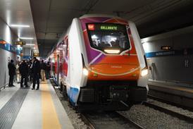
- CAPTION: Valuable lessons have already been learnt from trials with Japan's prototype three-car gauge-changing EMU
- Fig 1. Side view and cross-section through a wheelset of the Type A bogie with fixed axles. The rotor of the direct-drive traction motor is attached directly to the wheel, with the inner coil mounted on the axle sleeve
- Fig 2. Plan view of a wheelset in the Type B bogie, where the traction motor drives through a gearbox. The outer sleeve assembly is designed to slide along the axle
- Fig 3. The locking mechanism of the Type B bogie, showing the locking and release arms
- Fig 4. Two versions of the second-generation bogie have been built for bench testing, which is due to be finished later this year