


INTRO: The introduction of modern rolling stock requires comprehensive and accurate knowledge of clearance profiles throughout the network where it will operate. Innovative measuring systems will enable accurate data to be collected at up to 200 km/h
BYLINE: David M Johnson
Managing DirectorLaser Rail Ltd
INTRODUCTION of new rolling stock on an ageing rail network can pose all sorts of problems, as British franchisees have been discovering. In May, First North Western’s Class 175 Coradia DMUs were pulled out of traffic just a couple of weeks before they were due to start revenue service. Despite several months of test running, Railtrack withdrew their route clearance on several lines, pending expensive emergency work to cut back platform edges. Much debate ensued between builder, operator, leasing company and infrastructure owner over the division of responsibility for ensuring the new trains fitted the route profile.
In an increasingly contractual industry, such issues are showing up the critical nature of loading gauge clearances. Commercial pressures are pushing engineers to maximise capacity for freight trains, or to operate passenger trains at higher speeds that require a larger kinematic envelope. The search for a softer ride may also result in greater body roll, whilst the design of new rolling stock frequently requires items such as yaw dampers to be placed in a congested area from a gauge perspective.
Existing methods
Computer simulation packages such as ClearRoute are commonly used to help with gauging issues, including applications for Railtrack route acceptance for the Siemens Class 332 for Heathrow Express, the Adtranz Turbostar and Electrostar families, and the Alstom Juniper and Coradia multiple-units. The same packages are being used to approve the tilting trains for both Virgin’s West Coast and CrossCountry franchises. However, implicit in the use of these systems is the availability of accurate and up-to-date network profile data. More than once in recent years, Railtrack has come under fire for its inadequate knowledge of its own infrastructure.
The increasing need for accuracy has driven up the degree of sophistication of measuring systems. Early measurements were taken using simple wooden frameworks to check bridges and tunnels, and some of these gauges are still in use. Today’s measuring technology falls into two categories; manual tools and mobile systems.
Manual tools range from simple tape measures through to precision laser profiling systems. They are primarily aimed at local analysis of particular structures - either as part of a strategic process, or for precise measurement of structures where a more cursory screening has identified potential problems. Designed to be portable and safe for use on operational track, they provide an accurate record of the structure shape. But they are relatively slow, taking several minutes per structure. For most operators, the volume of measurement required precludes the use of manual systems for regular monitoring and auditing of the network.
Mobile structure gauging offers a faster process, although the various systems in use have their own limitations. In the mid-1980s British Rail developed an optical Structure Gauging Train, which is now owned by Railtrack and operated by Serco (RG 5.83 p353).
The SGT performs a continuous measurement of the infrastructure and associated track geometry at up to 80 km/h. A plane of white light is projected from the optical car, creating an image which is monitored by a number of video cameras and then triangulated to create a measured profile. This vehicle produces composite profiles every 5m, recording all objects with a minimum longitudinal length of 100mm. Although the concept remains valid, the slow analogue technology and the need to operate at night restrict its use. Additionally, the analogue nature of the system prevents accurate two-dimensional calibration, which would improve accuracy.
The combined disadvantages of night-time only operation and 80 km/h running mean that it is difficult to provide paths, particularly on routes where capacity improvements are required.
Recent developments centre on laser-based scanners, which trace a helix through structures. At a relatively slow speed, the helix is capable of providing information that is as complete as the SGT. However, as speed increases, the helix pitch lengthens, reducing the longitudinal resolution. Scanners operating at 200rev/sec are now available, but to maintain a 100mm longitudinal resolution, the operational speed is limited to 72 km/h. Experience has demonstrated that accuracy is considerably improved by overlapping scans, using a 10 mm diameter laser beam, which restricts speed to just 3·6 km/h. Such systems are therefore most appropriate for screening at modest speeds or accurate measurement at very slow speeds.
Laser gauging vehicle
In 1998, Laser Rail assembled a project team to develop a vehicle capable of accurate, daylight operation at up to 200 km/h. The project has been granted a ’Smart’ award from Britain’s Department of Trade & Industry, which has partially funded some of the more novel technology.
The Laser Gauging Vehicle combines various technologies to measure the structure profile in relation to the rail datum at high speed and to very high resolution. The measuring equipment is being designed as a stand-alone device which can be fitted to a variety of chassis, starting with a prototype road-rail vehicle.
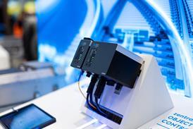
Each structure is illuminated with a slice of visible laser light generated from a number of projectors, but of an uncommon wavelength matched optically to the measuring cameras. Conforming to laser safety Class 3a, the system will be eye-safe and rated similarly to commonly-used construction lasers. Measuring is performed by a number of specially-developed high-performance digital cameras, which have integral processors capable of pre-processing vast quantities of information (Fig 1).
Because the data is digital, complex algorithms can be used to provide accurate calibration in two dimensions, enhancing the competency of data gathered by identifying structure shapes.
Related systems on the vehicle define its position and rudimentary track geometry. Accurate position definition allows cross-referencing with infrastructure databases, and enables any change in shape to be detected from one run to another. Basic track geometry (cant and curvature) provides the required input into the determination of kinematic and dynamic envelopes.
The system is designed to be configured for different resolution, accuracy and speed as required. For typical high-speed applications up to 200 km/h, a longitudinal resolution of 22mm should be achievable, with a horizontal precision of 5mm and a vertical precision of 25mm. At a speed of 50 km/h, a 28mm longitudinal resolution could be obtained with a lateral and vertical precision of 5mm.
A prototype mounted on a road-rail chassis is undergoing initial trials, and should be available for low-speed contract work within two years. The prototype is currently undergoing static and dynamic testing, aimed at proving and validating the measurement system. This will be followed by type-approval and safety approval to enable operation on the British rail network.
Future applications under consideration include a simple road-rail vehicle similar to the prototype, dedicated measuring coaches able to operate in train formation, and self-contained systems which could be mounted on revenue service trains. n
CAPTION: Laser Rail’s prototype Laser Gauging Vehicle is currently undergoing static and dynamic tests to validate and calibrate the measuring
equipment
CAPTION: Detailed measurements of a single structure can be obtained with advanced manual gauging tools such as Laser Sweep
CAPTION: Fig 1. Diagram of Laser Projection and Camera System showing how Each structure is
illuminated with a slice of visible laser light generated from a number of projectors
CAPTION:
Laser Rail would welcome input from potential users of the measuring systems about their likely requirements. The author can be contacted at david@laser-rail.co.uk
Laser gauging offers rapid route assessment
Technology is being developed to permit railways to measure infrastructure clearances at up to 200 km/h. Accurate clearance profiles are becoming increasingly important as more types of rolling stock are introduced, often with dynamic characteristics that exploit clearances to the limit. A prototype road-rail laser gauging vehicle uses laser light matched optically to high-performance digital cameras with integral processors. Static and dynamic tests have generated encouraging results, and plans envisage mounting the equipment on simple vehicles, dedicated measuring coaches or service trains.
La mesure du gabarit au laser offre un rapide diagnostic de ligne
Une technique est en cours d’élaboration afin de permettre aux réseaux de mesurer à des vitesses allant jusqu’à 200 km/h le gabarit laissé libre par l’infrastructure. Des relevés de gabarit d’infrastructure précis sont de plus en plus importants à mesure que des nouveaux types de matériels roulants sont mis en service, souvent avec des caractéristiques dynamiques qui exploitent le gabarit des obstacles jusqu’à la limite du possible. Un véhicule rail-route prototype chargé de mesurer le gabarit utilise un rayon laser dirigé vers une caméra numérique à haute performance, à processeur intégral. Des tests statiques et dynamiques ont produit des résultats encourageants et un projet prévoit le montage de cet équipement sur de simples véhicules, des voitures spéciales de mesure ou des trains de service
Lasermesstechnik erlaubt schnelle Streckenbeurteilung
Es sind Entwicklungen im Gange, welche es den Bahnen erlauben, Lichtraumprofile mit Geschwindigkeiten bis zu 200 km/h zu messen. Genaue Profilmasse werden zunehmend wichtig, da mehr und mehr verschiedene Fahrzeuge eingeführt werden, zum Teil mit dynamischem Verhalten, welches das verfügbare Profil maximal nutzt. Ein Prototyp eines Strasse-/Schiene-Messfahrzeuges setzt Hochleistungs-Digitalkameras mit integrierten Bildprozessoren mit entsprechend eingestellten Lasern ein. Statische und dynamische Versuche haben vielversprechende Resultate gezeigt, und es bestehen Pläne, diese Einrichtung auf einfachen Fahrzeugen, eigentlichen Messwagen oder Dienstzügen zu installieren
Guías por l